
- All
- Product Name
- Product Keyword
- Product Model
- Product Summary
- Product Description
- Multi Field Search

Views: 148 Author: Site Editor Publish Time: 2026-06-01 Origin: Site


Form factors for modern electronics are shrinking faster than ever. From 1U rack servers to dense power inverters, components generate massive heat in highly confined spaces. As Total Dissipated Power (TDP) rises, traditional thermal solutions quickly hit a hard performance wall. Standard coolers simply lack the surface area needed to transfer heat away from critical device junctions. You need a solution maximizing cooling capacity without expanding the physical footprint.
A high fin density heat sink solves this spatial constraint by exponentially increasing the available convective surface area. However, successfully deploying one requires careful engineering. You must balance base thermal resistance, manufacturing technology limits, and airflow static pressure. In this guide, we break down exactly when to specify high-density designs. We examine the manufacturing processes making them viable. Finally, we explore the vital engineering trade-offs required for reliable electronics thermal management.
Surface Area vs. Airflow: High fin density maximizes heat dissipation area, but requires pairing with high static pressure cooling to prevent airflow "shunting."
Manufacturing Dictates Limits: Technologies like skiving and cold forging push aspect ratios up to 50:1, overcoming the dimensional limitations of standard extrusion.
System-Level Evaluation: Specifying a high density heat sink requires calculating base thermal resistance ($R_{sa}$) alongside environmental variables like altitude derating.
Hardware engineers constantly fight against spatial limitations. In densely packaged environments, expanding the physical footprint of a cooler is rarely an option. You cannot simply increase the X and Y dimensions on a crowded motherboard. Z-height restrictions in blade servers or small form factor (SFF) PCs strictly limit cooler tallness. We only have one variable left to manipulate. We must increase the total surface area within the existing three-dimensional volume.
Understanding this requires looking at the thermal circuit. To maintain safe operating junction temperatures, engineers calculate total thermal resistance. We express this as $R_{ja} = R_{jc} + R_{cs} + R_{sa}$. Here is how these components break down:
Junction-to-Case ($R_{jc}$): The internal resistance of the semiconductor package.
Case-to-Sink ($R_{cs}$): The resistance of the thermal interface material bridging the component and the cooler.
Sink-to-Ambient ($R_{sa}$): The resistance of the cooler transferring heat into the surrounding air.
You have little control over package resistance. You can only optimize interface material slightly. To significantly lower total resistance, $R_{sa}$ must drop. High density arrays achieve this directly. They pack dozens of thin cooling fins into tight spaces, drastically increasing the convective surface area. This maximizes the heat transfer rate into the ambient environment.
Furthermore, dense configurations help break thermal boundary layers. Air naturally clings to flat surfaces, creating an insulating layer of warm fluid. Specific geometries like micro-channels or staggered pin layouts disrupt this layer. They induce micro-turbulence. This turbulence mixes the fluid rapidly, accelerating heat extraction far better than flat, sparse profiles.
Adding more surface area seems like an obvious win. However, extreme density introduces serious implementation risks. The most common engineering mistake is upgrading a cooler's density while ignoring system aerodynamics.
Tightly packed fins create massive aerodynamic resistance. Airflow behaves like electricity; it always follows the path of least resistance. If you pair a dense array with a standard airflow-optimized fan, you will trigger the "shunt" effect. The fan lacks the pressure to push air through the narrow gaps. Instead, the air bypasses the array entirely. It flows around the edges, leaving the internal channels starved of cool air. Thermal performance immediately collapses.
To overcome this, a dense cooler mandates high static pressure cooling. You must forcefully push air through the restrictive gaps. System designers must specify specialized fans or centrifugal blowers. These fans measure their performance in millimeters of water (mmH2O) rather than just cubic feet per minute (CFM). They use aggressive blade angles to force fluid through heavy restriction.
This requirement introduces a distinct trade-off. Generating high static pressure requires higher fan RPMs. Higher speeds create louder acoustic profiles. Blades chopping through dense air generate noticeable vibrations. You must carefully weigh your thermal headroom against acoustic compliance targets. Prioritize fan longevity, as high-speed operation degrades fan bearings much faster.
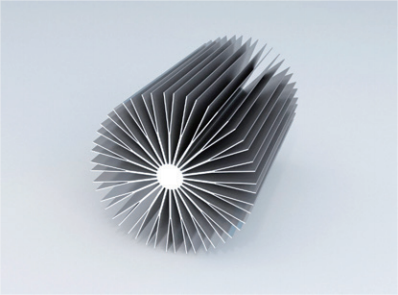
Producing closely packed cooling arrays requires advanced fabrication methods. Standard machining cannot mill deep, narrow channels efficiently. Instead, the industry relies on specific manufacturing techniques. Each balances thermal performance against production feasibility.
Aluminum heat sink extrusion serves as the industry baseline. Manufacturers force heated metal through a custom steel die. We typically use a 6063 aluminum heat sink alloy for this process. It offers an excellent blend of thermal conductivity (~200 W/m·K) and physical workability. However, extrusion faces strict physical limits. Depending on tooling precision, the aspect ratio maxes out between 10:1 and 40:1. Pushing the die beyond these limits causes the steel tooling teeth to snap under extreme pressure.
When extrusion hits its limit, engineers turn to skiving. A skived fin heat sink is carved directly from a solid metal block. A sharp cutting blade shaves thin layers of metal, peeling them up to form vertical fins. This process offers massive advantages. It leaves zero thermal interface resistance between the base and the fins, as they remain one continuous piece of metal. Skiving achieves ultra-thin profiles down to 0.25mm. It unlocks extreme aspect ratios up to 50:1. It remains the ideal choice for cooling highly localized hotspots.
Folded fin arrays use a completely different approach. Manufacturers stamp continuous sheets of thin metal into accordion-like structures. They then attach these folded sheets to a separate baseplate. We secure them using specialized soldering, brazing, or thermal epoxy. This method crams massive surface area into lightweight packages. Folded arrays can increase heat transfer rates by up to 30% over traditional extrusions within identical volumes. However, you must account for a slight thermal penalty. The bonding joint between the fold and the base introduces minor interface resistance.
Manufacturing Method | Max Aspect Ratio | Fin Thickness Limit | Base-to-Fin Resistance | Best Use Case |
|---|---|---|---|---|
Extrusion (6063 Alloy) | Up to 40:1 | ~1.0mm | Zero (Single Piece) | High-volume, cost-sensitive cooling. |
Skived Fin (Al / Cu) | Up to 50:1 | Down to 0.25mm | Zero (Single Piece) | Extreme localized hotspots, limited height. |
Folded Fin Assembly | Exceeds 50:1 | Down to 0.1mm | Slight (Bonding Joint) | Lightweight applications requiring massive area. |
Selecting the right cooling hardware requires rigorous evaluation. Engineers cannot rely on visual inspection or basic dimensional checks. You must evaluate specific physical metrics to ensure reliable thermal performance.
First, analyze the aspect ratio and fin pitch. The aspect ratio measures the fin height divided by the gap between fins. Tighter pitches drastically increase cooling surface area. However, they equally restrict airflow. You must cross-reference your chosen pitch against the fan's maximum static pressure curve. If the gap is too tight, the fan will stall.
Next, evaluate material thermal conductivity versus total mass. Pure copper delivers exceptional thermal conductivity (nearly 400 W/m·K). It moves heat incredibly fast. Yet, copper adds immense weight and cost. Aluminum alloys provide structural lightness and lower costs. Some emerging designs use hybrid materials. They integrate carbon-based matrices or embed Phase Change Materials (PCM) into the base. These hybrids absorb transient heat spikes without adding excessive mass.
Finally, you must calculate environmental derating factors. Many engineers completely overlook this crucial metric. Cooling capacity drops significantly in aerospace, automotive, or high-altitude telecom applications. Higher altitudes feature lower air density. Less dense air absorbs and carries away less heat. You must oversize your cooling arrays using specific altitude derating multipliers to prevent failure.
Example: Altitude Derating Summary Chart | ||
Altitude Level | Air Density Ratio | Thermal Derating Multiplier |
|---|---|---|
Sea Level (0m) | 1.00 | 1.00 (Baseline) |
1,500m (Approx. 5000 ft) | 0.86 | 0.90 |
3,000m (Approx. 10000 ft) | 0.74 | 0.82 |
Moving from theoretical thermal models to physical production exposes several operational risks. Sourcing high-performance coolers requires careful planning to avoid late-stage manufacturing failures.
Consider tooling costs and delivery lead times. Skived and CNC-machined prototypes skip heavy tooling phases. They offer lower upfront costs and faster initial delivery. However, their per-unit price remains high at scale. Conversely, custom extrusion dies demand significant upfront investment and longer lead times. Once established, they dramatically lower the unit cost for mass production.
Thermal Interface Material (TIM) matching poses another severe risk. A highly engineered cooler remains useless if bottlenecked by poor TIM. Dense bases saturate with heat almost instantly. Standard silicone pastes often fail under this rapid thermal flux. They suffer from the "pump-out" effect during thermal cycling. Dense designs often require ultra-thin, high-performance phase-change materials. Some extremely dense copper solutions require liquid metal interfaces to keep the base from overheating.
Lastly, address mechanical mounting constraints. Dense fin arrays, particularly copper variations, are heavy. Relying on standard plastic push-pins invites disaster. Heavy rigid assemblies require secure, industrial mounting methods. You must specify spring-loaded screws and specialized metal backplates. These mechanisms distribute the heavy load evenly. They prevent the printed circuit board (PCB) from warping over time and maintain consistent, vital TIM pressure.
High fin density arrays are indispensable tools for overcoming modern spatial constraints. They provide the massive surface area required to dissipate rising power loads in compact footprints. However, they only succeed when treated as part of an integrated system. They absolutely rely on high static pressure airflow to function correctly.
To implement them successfully, engineers should take immediate next steps. First, calculate the maximum allowable sink-to-ambient resistance ($R_{sa}$) for your device. Next, cross-reference this thermal envelope against your available system static pressure. Finally, select a manufacturing method—like extrusion, skiving, or folding—that satisfies both your thermal targets and your operational budget.
A: No. Performance only improves if the system can push air through the narrower gaps. If the fin gap becomes too small for your fan's static pressure to overcome, airflow completely stalls. The air bypasses the cooler, and thermal performance actually worsens.
A: Skiving carves fins directly from a solid metal block. It eliminates the thermal boundary layer between the fin and the base. Skiving also physical allows for much thinner fins and much higher aspect ratios than standard extrusion tools can pull without breaking.
A: Yes. The 6063 alloy remains the standard for extrusions due to its excellent workability and solid thermal conductivity. However, for extreme density needs beyond extrusion limits, manufacturers switch to 1000-series pure aluminum via cold forging or pure copper via skiving.